If you came to glm for a practical STEP-to-STL workflow, this guide explains how export refinement turns curved CAD surfaces into mesh triangles and how to check the result for faceted holes, oversized files, and printable detail.
An STL export fixes the smoothness of every hole and fillet as triangles. I use the part’s smallest important curves—not the file-size setting alone—to choose a sensible mesh, then inspect the result before printing.
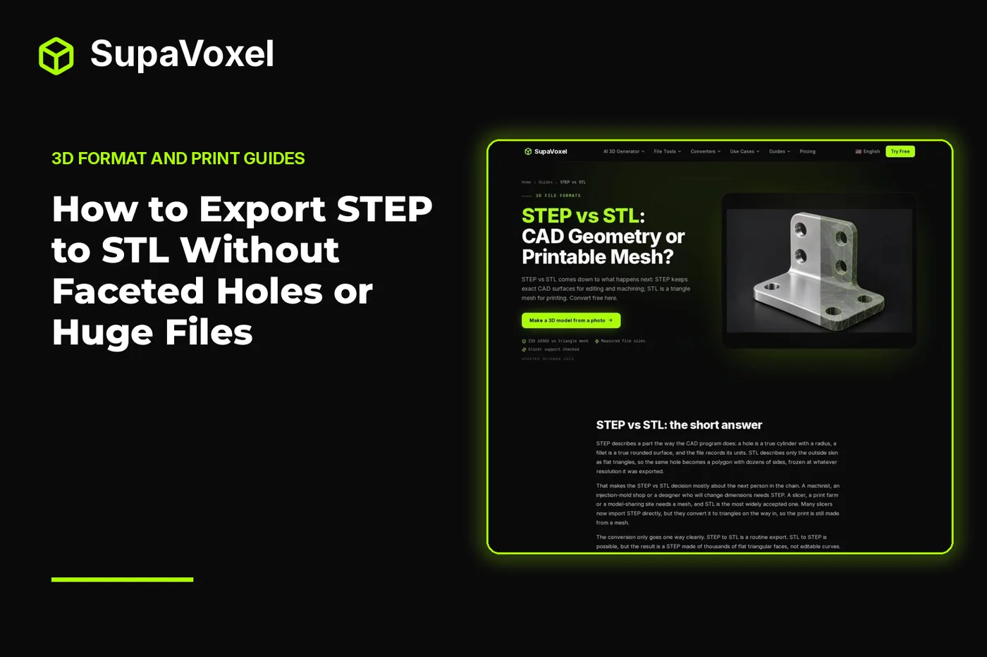
The short version
- The STEP vs STL guide shows how tessellation settings changed a bracket from a 73 KB STL to a 1.27 MB STL. More triangles did not change the underlying CAD part.
- Start with an STL export tolerance near 0.01 mm for a functional part, then inspect the smallest holes and fillets that matter to your print.
- Keep the STEP file. Once its exact curves have become STL triangles, a finer export of that STL cannot restore them.
- If you only need a printable mesh and cannot set export refinement in CAD, the browser converter provides a default mesh—but it has no resolution slider.
Read the bracket measurements before choosing a setting
Tessellation is the step where a CAD exporter replaces exact curved surfaces with flat triangles. A cylinder in STEP has a true radius. In STL, its circular edge is a chain of straight segments. The export settings decide how closely those segments follow the curve.
The guide’s test part was a 60 × 40 × 40 mm L-bracket with a 5 mm wall, 1.5 mm fillets and four 5.2 mm holes. Its STEP file was 175 KB. Exporting that same geometry at different settings produced:
- Coarse STL — 0.1 mm linear tolerance, 0.5 rad angular tolerance; 1,462 triangles; 73 KB.
- Fine STL — 0.01 mm linear tolerance, 0.2 rad angular tolerance; 5,290 triangles; 265 KB.
- Very fine STL — 0.001 mm linear tolerance, 0.1 rad angular tolerance; 25,340 triangles; 1.27 MB.
The coarse file is smaller than the STEP; the very fine file is much larger. That is not a contradiction. STEP stores the bracket’s surfaces as CAD geometry, while STL must list the triangles used to approximate them. Increasing mesh detail adds triangles without adding design features.
Linear tolerance limits how far the mesh may depart from a curved surface. Angular tolerance affects how the exporter divides surfaces as their direction changes. Lower settings generally mean a closer approximation and a larger mesh. The useful question is not “How fine can I export?” but “Can I see or print a difference on this part?”
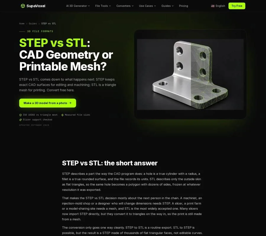
The STEP vs STL guide compares the bracket’s exact CAD geometry with STL exports at different tessellation settings.
Inspect the STEP before you make the mesh
1. Confirm that the source contains the part you expect. An export setting cannot fix a missing body. If a supplier sent the file, I open it first in CAD or use 3D Studio’s STEP viewer to see the solids, their colors when present, and the model’s overall dimensions. The viewer accepts .step and .stp files and displays the bounding box in mm, cm or inches.
2. Find the curves that deserve attention. Look at small holes, short fillets and prominent round edges. A broad flat face gains little from extra triangles; a small circular opening can look polygonal when exported too coarsely. Decide which features need smooth edges before changing any tolerance.
3. Treat the viewer’s wireframe as a preview, not an export verdict. The viewer turns STEP surfaces into triangles so it can draw them. Wireframe makes those display facets visible, but its triangle count describes the display mesh, not necessarily the STL your CAD export will write. Use it to understand where tessellation happens, then inspect the actual exported file.
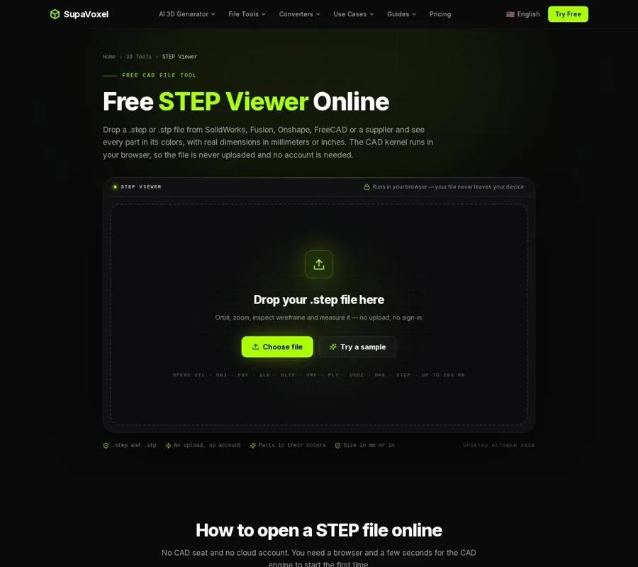
The STEP viewer shows the model’s overall size and lets you examine the displayed surface mesh in wireframe.
Export from CAD when a small curve needs more detail
1. Save the STEP or native CAD source. Make the STL as an output copy. If the mesh proves too coarse, returning to the exact surfaces gives you a clean way to export again.
2. Choose a starting refinement rather than the finest available setting. For functional parts, the guide recommends a chordal tolerance near 0.01 mm; it notes that small fillets can show facets at 0.1 mm. The bracket measurements show the cost of going finer: moving from the fine to the very fine settings increased its mesh from 5,290 to 25,340 triangles.
3. Export and examine the result at the features you identified. Rotate the mesh so you can see the rims of holes and the transitions across fillets. A circular opening that looks acceptable from above may show obvious straight sides at an angle. If a relevant curve is visibly faceted, go back to CAD and refine the export. If it already looks smooth for the intended print, a much larger file may offer no useful benefit.
Do not judge resolution by file size alone. A part with more curved surface can need more triangles than a mostly flat bracket. Conversely, an enormous triangle count does not prove that the dimensions or orientation are correct. Mesh detail answers one question: how closely the triangles follow the source surfaces.
Use the browser converter when its default mesh is enough
If you have a STEP file but no CAD export controls, 3D Studio’s STEP to STL converter reads .step and .stp, previews the part and downloads an STL. It is free to use, needs no sign-up and processes the file in your browser. It accepts files up to 200 MB.
1. Drop in the STEP file and check the preview. The converter shows the triangle count and output size. STEP declares its units; the converter writes millimeters, including when the input STEP uses inches. Read the displayed dimensions rather than assuming the part has arrived at the intended size.
2. Check orientation and wireframe. The Z-up option places the part for printing. Wireframe lets you inspect facet density before downloading. Pay particular attention to a small hole on a much larger part: the converter uses default meshing tolerances that adapt to part size, and it does not offer a resolution slider.
3. Download the STL and open it in your slicer. Binary STL is the default; ASCII is available if another tool requires readable text. If a critical curve remains too polygonal, export from CAD with a higher refinement setting instead of trying to sharpen the finished STL.
An assembly needs another check. The converter puts its bodies into one STL file while keeping their positions. If you intend to print pieces separately, exporting each as its own STEP file before conversion is the clearer route.

The converter previews the tessellated part and shows its size before the STL download.
Check the exported mesh, not just the export dialog
Import the STL into the slicer you plan to use. Confirm its overall dimensions first: STL has no unit field, and slicers commonly treat its coordinates as millimeters. A smooth-looking hole is no comfort if the entire part arrived at the wrong scale.
Then inspect the small curves at an angle and look at the sliced preview. The mesh view tells you whether the facets are already built into the file; the slice preview tells you how the slicer will use that geometry. If the STL edge is visibly polygonal, changing print settings cannot turn it back into an exact CAD circle. Return to the STEP and export a finer mesh.
Also check that every intended body is present and positioned for printing. Resolution, scale and completeness are separate checks. A beautifully tessellated bracket with a missing component is still the wrong export.
Keep the source for the next revision
The clean path runs from exact CAD surfaces to triangles. It does not run cleanly backward. 3D Studio’s STL to STEP converter can make a closed, faceted STEP solid from an STL for CAD work, but its curved areas remain flat faces. It cannot recover the original editable hole radius or fillet.
That matters when a fit changes later. Keep the native CAD file and STEP alongside the print mesh. If you need a different hole size, edit the source geometry and make a fresh STL. If you need only a smoother print surface, export that source again at a finer tolerance. Those are different jobs, and keeping the source makes both straightforward.
FAQ
Should I always use the finest STL export setting?
No. The bracket grew from 265 KB at the fine setting to 1.27 MB at the very fine setting. Start near 0.01 mm for a functional part, inspect its important curves, and refine only if the mesh needs it.
Why does my hole look polygonal even though the STEP is round?
The STEP stores an exact cylinder, but the STL exporter approximates it with triangles. Re-export from the STEP with finer tessellation if the facets matter to the print.
Can I fix a coarse STL by converting it back to STEP?
Not by conversion alone. A STEP made from that STL retains the faceted shape; it does not reconstruct the original cylinder. Use the original CAD or STEP file for a cleaner export.