Readers searching for glm will find a practical walkthrough for turning a dense 3D scan OBJ into an STL that can be sliced. It covers cleanup, unit checks, conversion, and inspection before printing.
A scan can look complete on screen yet leave a slicer guessing where the solid begins. I check the mesh’s density and scale first, then convert it to STL and inspect the gaps that scanning tends to leave behind.
The short version
- Keep the scan’s OBJ as your editable source. Simplify excessive geometry before export, but preserve the surface detail the print needs.
- Use 3D Studio’s OBJ to STL converter to choose the OBJ’s source units and inspect the resulting size before downloading.
- Conversion preserves the surface shape, not scan colors, textures, or separate OBJ groups. It does not make an open scan watertight.
- Check the STL for holes and loose pieces, repair what can be repaired, and inspect the slice before printing.
Step 1: Decide whether the scan needs cleanup first
A scanner records the surfaces it can see. The underside of an object resting on a table may be missing; a narrow recess may be incomplete. At the same time, the visible surface can contain far more triangles than the print needs. Those are different problems: reducing triangles makes the mesh easier to handle, while closing gaps gives the slicer an inside and an outside.
I start by looking at the OBJ in a modeling app. Is the silhouette complete? Are there isolated fragments away from the object? Is a missing area small enough that a patch could follow the surrounding surface, or is an entire side absent? I would remodel or re-scan a substantially missing side rather than ask a repair tool to invent it.
For a very dense scan, simplify the mesh before conversion. The aim is not to make every facet disappear. Compare the reduced version with the original around edges, lettering, and shallow relief—places where lost triangles can change the printed shape. A scan with millions of polygons may benefit from decimation, but triangle count alone does not tell you how much detail is safe to remove.
Keep the original OBJ. If cleanup removes a feature you later need, the STL will not give you the scanner’s colors or original surface data back.
Step 2: Establish the print size before exporting
OBJ has no field that declares its units. A coordinate is just a number until you decide whether the scan was measured in millimeters, centimeters, meters, or inches. STL has no unit field either, so a mistaken assumption can travel through conversion and only become obvious in the slicer.
The converter initially reads the OBJ as meters. Check its displayed print dimensions against a dimension you know from the object or the intended print. If the result is implausibly large, change File units rather than compensating with an arbitrary scale in the slicer. The output panel lets you see the consequence before downloading.

The converter shows the model alongside the controls used to check its print size before export.
For an irregular scan, height alone can be misleading. Think about its overall width and depth as well: a correctly sized object should make sense in every dimension. If you cannot establish the scan’s original units, the Scale to 100 mm tall control offers a deliberate starting size, but treat that as a sizing decision—not evidence of the object’s real dimensions.
Check orientation in the preview, too. The converter prepares the result Z-up for printing. If an OBJ was already exported Z-up and appears to be lying on its back, turn Z-up for printing off. Set size and orientation here so the STL you save is the one you intend to slice.
Step 3: Convert the surface, then question the result
Drop the OBJ into the converter and download the binary STL once the dimensions and orientation look right. The OBJ alone supplies the geometry. An MTL file and textures can color the preview when supplied, but they cannot put color into the STL.
The converter splits quads and larger polygons into triangles. It also combines OBJ groups into the output geometry; group names and object organization do not survive. That matters if a scan includes a main object plus separate stray fragments: do not assume that losing the group labels removes those fragments.
Nor does triangulation close a surface. It describes the faces already present in a form the STL can store. A hole under the scan remains a hole, and a thin open sheet does not acquire printable thickness just because it has become an STL. Think of conversion as a format and scale check, not a mesh-health check.
If you need separate printable parts, split them in your modeling app before this export. If you need scanner color for another project, keep the source files alongside the STL rather than treating the print file as your archive.
Step 4: Inspect gaps before attempting repair
Open the converted file in 3D Studio’s STL repair tool. Its report distinguishes holes, open edges, non-manifold edges, flipped faces, and separate shells. Problem edges appear in red, making it easier to tell a small gap from a large missing region.
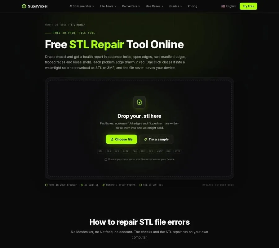
The health report and highlighted edges help locate defects before changing the scan.
An open edge belongs to only one triangle, so the surface stops there. A non-manifold edge is shared by too many faces, leaving the inside and outside ambiguous. Flipped faces point against their neighbors. A slicer may guess its way past some of these defects, but its guess can mean a missing wall or an unexpected filled area.
Read the report before pressing Repair mesh. The repair process reconnects coincident corners, removes problematic faces, makes face directions consistent, and patches open loops. Then it runs the health check again, so compare the original and result rather than assuming the operation succeeded.
Pay particular attention to Remove tiny floating pieces. It is on by default and deletes loose shells smaller than 1% of the model’s triangles. That is useful for scanning debris, but turn it off if small separate features are intentional. Also inspect any large patched area: a repair patch follows the surrounding surface, which may produce the wrong shape where a scan is missing its base. Repair does not thicken walls, and overlapping closed shells can remain separate.
Check the slice, not just the file
A watertight report is an important checkpoint, not a print guarantee. Load the repaired STL into your slicer and inspect the layers around the areas that were missing or patched. Look for a continuous outline, expected internal fill, and small features that have not vanished.
Pay special attention to the bottom of a scanned object. A repaired opening may be closed but rounded where you expected a flat contact surface. If the object does not sit as intended, fix the base geometry before printing. Likewise, a wall can be watertight yet too thin for the chosen print setup; mesh repair does not add material to it.
If the slice looks wrong, return to the scan or the repair comparison. Check whether simplification removed a feature, whether a floating piece was deleted, or whether the missing area needed modeling rather than an automatic cap. Re-exporting from a better source is more dependable than repeatedly asking the slicer to interpret a damaged one.
Keep the right file for the next job
The repaired STL is for slicing and sharing a plain printable shape. Keep the original OBJ, plus any cleaned version, if you expect to edit the scan again. An STL carries triangles and normals, but not the scan’s UVs, textures, or color.
If an STL is all you have and you need to bring it into a modeling or texturing workflow, 3D Studio’s STL to OBJ converter writes an upright OBJ and converts the assumed millimeter print scale to meters. It cannot restore scan data that the STL never held; you would need to unwrap the mesh before painting a texture.

The reverse converter prepares print geometry for use in a modeling app, without recreating lost scan textures.
For a web or AR preview instead, the STL to GLB converter changes print-scale millimeters to GLB’s meter scale and turns the model Y-up. Its output has a neutral gray material because the STL has no color to carry across. That makes it a useful preview of the printable shape, not a substitute for the original colored scan.
FAQ
Does converting my scan’s OBJ to STL fix its holes?
No. Conversion writes the existing surface as STL triangles. Check the output for open edges and holes, then repair or remodel the missing areas as appropriate.
Should I simplify before or after repair?
For an extremely dense scan, simplify before conversion if you can do so without losing needed detail. If a dense file still resists repair, reducing its triangle count before trying again is also an option. Compare each result with the source.
Why does the repaired model still slice badly?
Watertight geometry can still have thin walls, an unsuitable patched base, or separate overlapping shells. Inspect the slicer’s layers and return to the source mesh when the shape itself needs correction.